Laser Sentry for Press Brake Safety
Laser Sentry for Press Brake Safety
Laser Sentry for Press Brake Safety
PART #
Laser Sentry for Press Brake Safety
Laser Sentry for Press Brake Safety
Laser Sentry for Press Brake Safety
Machine Safety Device to Prevent Workplace Injuries
Details
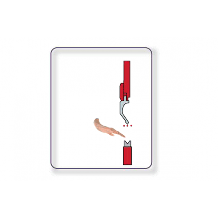
The Laser Sentry system is a cutting-edge safety device, a Presence Sensing Device (PSD) featuring laser guides that ensure the safety of a brake press operator while employing the precision of lasers directly surrounding the die. If a foreign object is detected, the laser technology will immediately retract the die.
Complete Laser Sentry System Includes:
Brackets
Bolts
Absolute Position Sensor
Instruction Manual
Nema 4 Enclosure
Laser Sentry is an OSHA compliant machine safety device system proven to reduce the risk to your workers’ well-being and to your business as a whole!
Laser Sentry – Press Brake Safety Features
- User display and keypad: Plain English interactive menu. Mode and status of all functions are displayed on the screen at all times. Comprehensive plain English error messaging. Optional wide screen portable touch panel.
- Personnel Protection: Three Horizontal Beams scan center, front and back of forming die, protecting front and back of the die. Beam alignment is non-converging. That is, the three beams are parallel and each has its’ own receiver. The laser beams are pulsed at a certain high frequency to prevent outside light source interference and false signals.
- Supervisory Control: Up to 10 operator passwords can be assigned and allows access to normal machine operations. One supervisor password is provided. The supervisor may control, change and assign operator passwords and access machine setup parameters. One master password is provided. The master password is for the owners and gives them access to everything, including changing of the supervisor password. Note: The use of passwords for operating personnel may be turned ‘OFF’ by the supervisor or owner. They do this fully at their own risk and responsibility. If the USER password function is turned ‘OFF’ any functions, such as box mode will be disabled on every start up.
- Machine Disable: If an operator wants to leave his machine he/she may select “DISABLE MACHINE” from the function menu and the machine will be disabled until he/she re-enters their password or another authorized password is entered, this prevents unauthorized use of the machine.
- Ram Position Monitoring: A non-contact, absolute linear transducer with .0025 accuracy digitally transmits via RS 485 the exact ram position to the control. Even after a power failure the control knows exactly where the ram is. In the event of a broken cable or other transducer fault the control will immediately disable the machine in a safe mode and display the appropriate error message.
- Wavy Material Function: In the event the operator encounters ram stops due to a wavy piece of material, they can select from the menu, “WAVY MATERIAL” by turning this function to ‘ON’, if the laser beam is interrupted by a wave in the material after it reaches slow speed the ram will retract until the beam is no longer broken and then stop. If the operator repeats this three times the ram will complete the forming cycle. Should the wave not be encountered after the first time the ram will continue the form.
- Rear Beam Interference: In the event a part or the backgauge fingers interrupt the rear laser beam it may be disabled by selecting this function from the menu.
- Box Forming Mode: When forming box and tray shapes the front laser beam will be broken by the upturned flange once the part is rotated 90 degrees for the next bend. The front beam may be temporally muted so that the part can be formed. Turn ‘BOX MODE’ to ‘ON’ from the menu. When done forming these types of parts turn the ‘BOX MODE’ back to ‘OFF’ for the safest operating mode.
- Part in Die Detection: When first setting up the machine for a particular part the ram is lowered until the center beam is interrupted by the material placed on the matrix die. This exact position is recorded and becomes the known position for the material. During normal forming operation, if the part is not detected on the matrix die the machine will reverse and display the error message “NO PART DETECTED”. This is to prevent the machine from cycling without a part in the die which could be a hazard because the open matrix of the die is exposed. If required to make particular parts this function may be turned OFF by the supervisor or owner.
- FREE CYCLE: In the event, especially during initial die setup, a part is not completely formed, the operator may press the CYCLE key on the keypad to override the PART DETECTION function. This will allow one stroke without detecting the material. If you require additional free strokes you must press the Cycle key each time.
- Vertical Laser Beam Alignment: When changing the forming tool you may have to reposition the laser beam so that it is 1/4″ below the forming die. An adjustable steel rule is provide on both the transmitter and receiver. The steel rule is set to zero upon installation. If you put a 3″ die in, you simply release the locking mechanism and move the transmitter and receiver to the 3″ mark on the ruler, tighten the locking mechanism and check to see that the beams are indeed scanning 1/4″ below the leading edge of the forming die.

